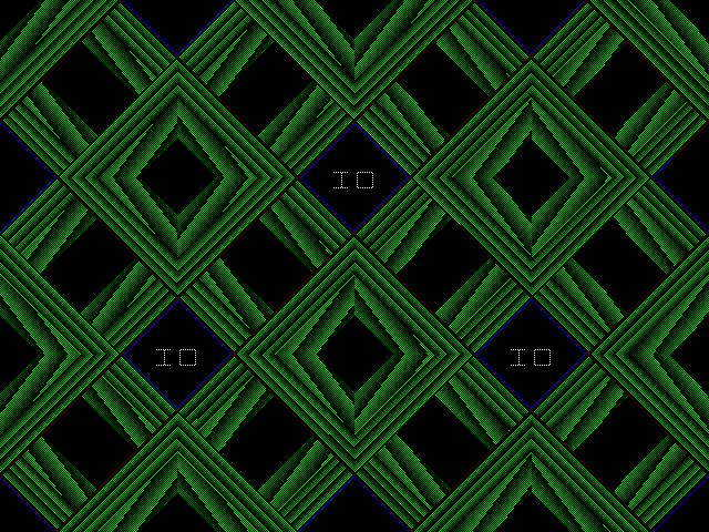
Arm IntrO Challenge
writing a demo for qemu-system-arm -M vexpress-a9. and possibly other arm emulators. or even devices for people that have/want to buy an arm dev board.Last year we held this challenge. Optimizing, algorithmic power, and learning some low level details combined into some good fun. Hence it was not completely surprising that when you were asked to choose what this year's challenge should be. That doing the same on an ARM platform won out. In addition to the reasons for last year's challenge many of us were also looking for a good excuse to get a bit more hands on with the ARM architecture. Do give it a try.
Unlike x86/PC systems when you buy ARM systems they don't typically have a bios. Hence no universal way of doing some of the most basic input and output tasks. That's why for now we will only focus on the system emulated by 'qemu-system-arm -M vexpress-a9'. We need to learn what(primecell clcd) is inside this virtual system. In order to communicate with additional hardware a cpu on an X86/PC system has a separate address space known as "io ports" (IN/OUT instructions and /proc/ioports), and memory mapped io (MMIO). An ARM system relies more heavily on MMIO. ARM systems also have the option to be extended with coprocessors. This mechanism is sometimes used to more hardware as well. The main difference though is that we need to learn how to express ourselves in ARM assembly instructions. ARM is a RISC architecture, even though the lines have blurred a bit, this will require us to be more verbose.
Challenge Rules:
- Look as impressive as possible
- Contain an IO logo
- less than or equal to 564 bytes
- Submission date: August 1st, 2012.
- Submission format: 564 bytes or less (source code optional but appreciated)
- Submit to: bla@netgarage.org or on irc
- There are no prizes. only bragging rights, submissions will be shown on this page
Entries
digitalcold

bin source
FreeFull


bin source
timpwn
bin source
invalid: blasty&inz (oversize 720 bytes)

bin source
This concludes the challenge. A big thanks to everybody that participated. I've decided to crown timpwn as the ,,winner''. I'll probably still process late entries if they show up.
Quickstart Guide and Documentation
Step 1: required tools
- qemu (tested on version 1.0.1)
- ARM assembler
wget http://ftp.gnu.org/gnu/binutils/binutils-2.22.tar.bz2
tar xjvf binutils-2.22.tar.bz2
./binutils-2.22/configure --target=arm-linux --prefix=$PWD
make
make install
PATH=$PATH:$PWD/bin
LD_LIBRARY_PATH=LD_LIBRARY_PATH:$PWD/lib
There are a few alternatives. Freefull reports that fasmarm works well too. In case you already have radare2 installed you can also (dis)assemble arm instructions using rasm2 -a arm.
Step 2: Getting Code To Execute
No BIOS to initialize hardware, read the first sector of the disks, find where to execute code from, etc. Qemu only allows you to start it using a "-kernel" option. It loads the binary into memory at 0x6001000 and uses a kernel calling convention on how to pass the commandline and where a potential initrd is loaded. However we will ignore all that and just pretend that the file we supply is part of rom where code execution starts. Execution will start at the first byte of the file.qemu-system-arm -M vexpress-a9 -kernel code.bin
e3a03a09        mov     r3, $0x9000
e3413000        movt    r3, $0x1000
e3a02041        mov     r2, $0x41
e5c32000        strb    r2, [r3]
So what does this code do? It stores 0x10009000 into the r3 register (there are 16 32bit registers r0->r15, r13,14,r15 are special, respectively stack pointer, link register, and program counter). Stores 'A' into r2. And finally stores r2 at address r3. Basically all we're doing is writing 1 byte to a memory location. And yes in plain ARMv7 instructions that takes 4 instructions and 16 bytes. Let's see if it works.
echo -ne "\x09\x3a\xa0\xe3\x00\x30\x41\xe3\x41\x20\xa0\xe3\x00\x20\xc3\xe5" > acode.bin
qemu-system-arm -M vexpress-a9 -serial $(tty) -kernel acode.bin
Well to be perfectly honest I fibbed a bit for the sake of simplicity. You can actually do it in 3 instructions or 12 bytes.
e3a03a09        mov     r3, $0x9000
e3a02041        mov     r2, $0x41
e7c32e02        strb    r2, [r3, r2, lsl $28]
In a lot of other instructions a range of -2048->2047 is a very inefficient use of bits. So in instructions like AND instead of the 12 bit immediate value an 8bit immediate value is stored and 4 bits are used as a shift count. allowing the byte to be shifted to any even position in the register.
This was exploited here to reduce the code size. The strb instruction stores r2 at (r3 + (r2 << 28)), which modulo 32bit comes down to 0x10009000. In comparison, storing 0x41 at address 0x10009000 on x86 using its variable length encoding takes 8 bytes.
We'll also want an endless loop instruction so when debugging we can halt execution at specific places.
[condition code][101][store return address][24bit offset]
0xeafffffe
Step 3: Setting Up Debugging
If you want some more advanced debugging capabilities than writing debug messages to the serial port, and using endless loops to halt execution, you can install gdb with support for remote arm targets. You can verify this by typing "set arch" in gdb and checking if arm is listed among the possible architectures.Same as on x86 we can use gdb to debug code running on our qemu system. We simply add -s and -S to the command line. One prevents the cpu from being started the other listens for gdb on port 1234.
qemu-system-arm -M vexpress-a9 -serial $(tty) -kernel acode.bin -s -S
gdb
set arch arm
target remote :1234
Step 4: Discovering The Hardware
Well from the name of the system we already know that it uses a versatile express base board. With a cortex-A9 cpu. Which in turn has an interface to use the AMBA bus. Connecting it among other things to the serial connection hardware. Namely the Primecell pl011 which we have used before to output the A character. Perhaps more importantly also Primecell pl111 clcd or color lcd. The display in other words. Other parts of the system can be found in the manual.Of course I didn't trawl through all those documents before starting. I cheated a bit by loading an ARM linux kernel onto the virtual device and checking /proc/iomem. The linux kernel get's its information from arch/arm/mach-vexpress. This contains the hard coded addresses for this board.
...
	}, {	/* PL011 UART0 */
		.dev_id		= "10009000.uart",
		.clk		= &osc2_clk,
	},
...
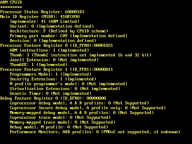
Beyond this, ARMv7 is a malleable platform, it has a lot of optional extensions, and different choices for settings. Which is great if you're building a system, but if you're writing low level code you need to know what's available. Fortunately the cpu does provide an identification scheme, as tot what features are implemented. Similar to the CPUID instruction on x86. I provide a program (source, screenshot) which reads the different registers and prints out the meaning of the different fields. Press space to advance in the program.
Step 5: Plotting Pixels
Having learned what video hardware is present, we need to know how to initialize it and use it. And it turns out it's very simple. timpwn beat me to the punch and got to plotting the pixels first. We'll take a few moments understanding this and compressing it down to a couple of assembly instructions.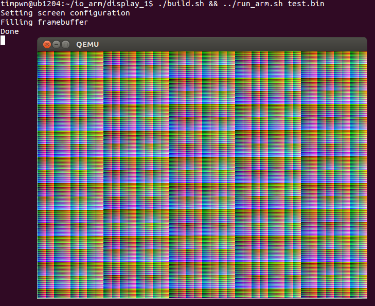
We have a Primecell pl111 clcd. Which the documentation tells us is mapped to 0x10020000. This means that the device's registers are accessible starting from that address. We can look at the linux kernel code to get a concise list of the registers and their offset relative to the base of 0x10020000. First we'll concern ourselves with these ones.
#define CLCD_TIM0               0x00000000
#define CLCD_TIM1               0x00000004
#define CLCD_TIM2               0x00000008
#define CLCD_UBAS 0x00000010
	mov r1, $0
	movt r1, $0x1002

	movw r3, $0x3F9C
	movt r3, $0x3F1F
	str r3, [r1, $0x0]

	movw r3, $0x61DF
	movt r3, $0x090B
	str r3, [r1, $0x4]

	mov r3, $0x1800
	movt r3, $0x067F
	str r3, [r1, $0x8]

	mov r2, $0
	movt r2, $0x6002
	str r2, [r1, $0x10]
#define CLCD_PL111_CNTL         0x00000018

#define CNTL_LCDEN              (1 << 0)
#define CNTL_LCDBPP1            (0 << 1)
#define CNTL_LCDBPP2            (1 << 1)
#define CNTL_LCDBPP4            (2 << 1)
#define CNTL_LCDBPP8            (3 << 1)
#define CNTL_LCDBPP16           (4 << 1)
#define CNTL_LCDBPP16_565       (6 << 1)
#define CNTL_LCDBPP16_444       (7 << 1)
#define CNTL_LCDBPP24           (5 << 1)
#define CNTL_LCDBW              (1 << 4)
#define CNTL_LCDTFT             (1 << 5)
#define CNTL_LCDMONO8           (1 << 6)
#define CNTL_LCDDUAL            (1 << 7)
#define CNTL_BGR                (1 << 8)
#define CNTL_BEBO               (1 << 9)
#define CNTL_BEPO               (1 << 10)
#define CNTL_LCDPWR             (1 << 11)
#define CNTL_LCDVCOMP(x)        ((x) << 12)
#define CNTL_LDMAFIFOTIME       (1 << 15)
#define CNTL_WATERMARK          (1 << 16)
	movw r3, $0x082B
	str r3, [r1, $0x18]
mov r0, $0
mov r3, $0x12c000

.redbars:
mov r1, r0
and r1, r1, $0xFF
str r1, [r2, r0]
add r0, r0, $4
cmp r0, r3
bne .redbars

hcf: B hcf
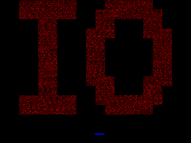
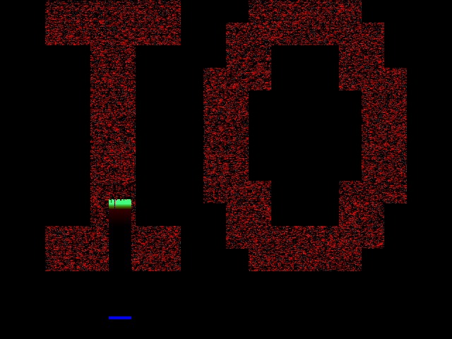
Example
Here is an example demo. It should display: .
.Near the end you'll find a constant 23, which you can change for some variations on this effect. I also provided a graphical Hello World by loading the vgafont. Which is too large to be usable in this challenge but you can't go without helloworld.
Step 6: Creating Source Files
We want to write code specific for this device. As such we need to tell the assembler what we're targeting..arch armv7-a .fpu neon .syntax unified .global _start _start:
The second part just defines a start symbol. While this isn't really necessary it prevents warnings being thrown by the next step.
miniBill provided a basic arm syntax highlighting for kate (kde advanced text editor). I thought this was a great
idea so I expanded it to cover the complete UAL syntax. The highlighting file is available.
Even if you don't use kate, it may be useful to check the list of pseuo-ops supported. The important ones are also covered in this quick reference (.req .balign, .word, .byte, .include, ...). The .req pseudo-op is very interesting. It allows you to assign temporary names to registers. When writing x86 code, our brains are pretty good at remembering where we store the different concepts in the 8 general purpose registers. But when you get r0-r15 and s0-s31 it can be quite a challenge. Rather than adding tons of comments you can do:
Even if you don't use kate, it may be useful to check the list of pseuo-ops supported. The important ones are also covered in this quick reference (.req .balign, .word, .byte, .include, ...). The .req pseudo-op is very interesting. It allows you to assign temporary names to registers. When writing x86 code, our brains are pretty good at remembering where we store the different concepts in the 8 general purpose registers. But when you get r0-r15 and s0-s31 it can be quite a challenge. Rather than adding tons of comments you can do:
xpos .req r10
add xpos, xpos, $10
Step 7: Building
Here's a Makefile that will automate the build process. (Keep in mind this is whitespace sensitive)
NAME=blaexample

TOOLPREFIX=arm-linux
all: ${NAME}.bin
	qemu-system-arm -M vexpress-a9 -m 128M -kernel $^

%.elf: %.s
	${TOOLPREFIX}-as $^ -o $@
%.out: %.elf
	${TOOLPREFIX}-ld -Ttext=0x60010000 $^ -o $@
%.bin: %.out
	${TOOLPREFIX}-objcopy -O binary $^ $@
%.objdump: %.out
	${TOOLPREFIX}-objdump -d $^  > $@
ldr r3, =0xffffffff
ldr r4, =0xcafebabe

ldr r1, =array
array:
.word 0xdeadc0de
Further Documentation: Instruction Sets
A good general introduction slideshow. The emulated cortex-a9 implements ARMv7-a. This profile supports two main instruction sets: ARM instructions and Thumb-2 instructions. Thumb-2 extends the Thumb instructions which were all 16bit, with 32bit ones to offer more complete functionality. The goal of Thumb/Thumb-2 is to increase the code density. Doing more with fewer bytes. However this also makes it more tedious to write by hand.You can switch between the two using blx instruction (among others).
	blx thumb_code
.thumb
thumb_code:
	@thumb instructions here
	blx arm_again
.arm
arm_again:
Besides these two main ones there's more. Jazelle DBX is a third execution state. It allows for direct execution of java bytecode. There is a BXJ instruction which branches to java. Complicated bytecode is handed back to software. However this mode has been largely deprecated. With newer processors handing back more(all) to the software layer in favor of the next option. As I understand it documentation on this state is lacking. Qemu does not implement this extension.
Instead of Jazelle DBX, a fourth execution state was created. ThumbEE. which modifies Thumb2 instructions to make them better suited as a compilation target for dynamic languages. A large part of these changes involve automated null pointer checks. It's marketed as Jazelle RCT. You can switch to ThumbEE state from Thumb state using ENTERX/LEAVEX
blx start
.thumb
start:
ENTERX
	@thumbEE code here
LEAVEX
These last two modes probably don't suit our purpose too well, but may be interesting to explore.
Further Documentation: Privilege Levels and Processor Modes
Analogous to the ring model on x86. ARM processors have different privilege levels. However they are numbered in the reverse order PL0 is the least privileged mode. If we peek at the CPSR via an attached gdb, we see that(gdb) info register cpsr cpsr 0x400001d3 1073742291
Further Documentation: Stack
There are twice as many general purpose registers in ARM than in x86 so it took us this long to develop a need for a stack. The stackpointer is stored in register r13. There is an alias "sp". The great thing about push, and pop is that you can push pop a selection of registers at a time. I modified the display initialization code to illustrate how this might work.
bl stack
.word 0x10020000	@ clcd pl111 base
.word 0x3f1f3f9c
.word 0x090b61df
.word 0x067f1800
.word 0x0000082b
.word 0x60020000	@ framebuffer base
stack:
mov sp, lr
pop {r2-r6,r8}
str r3, [r2, $0x0]
str r4, [r2, $0x4]
str r5, [r2, $0x8]
str r8, [r2, $0x10]
- a specific base register r13
- decrementing. stack grows down. (instruction suffix i incrementing. stack grows down but pop increments)
- post updating. basepointer points to first address used.(instruction suffix a after)
- the base register is updated at the end. (Indicated by the exclamation mark)
Further Documentation: Calling Convention
The default calling convention on ARM is to place the arguments to a function in r0,r1,r2,r3. If these can't hold the arguments a pointer to them must be passed in r0. functions have to preserve registers r4,r5,r6,r7,r8,r9,r10,r11. Since r13,r14,15 have a special purpose. That only leaves r12 to freely mess with in addition to the arguments registers when you don't need them any more. The return value is placed in r0.You are free to completely ignore this calling convention to save bytes. However if you're just starting out these are a good default.
Further Documentation: Conditional Execution
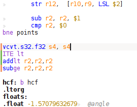
As mentioned before there is an important feature to be aware of called conditional execution. ARM instructions when suffixed with the letter S will set flags. There are 4 main flags. N (negative), C(carry), V(overflow), Z(zero or equal). 4 bits in the instruction encoding will determine whether or not an instruction is executed based on which of these are set. The flags are stored in the active PSR(program status register). Thumb instructions don't have the space to include 4 bit conditions, instead it uses a special instruction.thumb cmp r0, r1 ITE lt addlt r0, r0, $1 subge r0, r0, $1
Floating point instructions from the VFP extension also support conditional execution. However they use separate comparison instructions (VCMP, ...) and a separate set of flags which are stored in the top 4 bits of the FPSCR register. This register also controls others features of the fpu. For example what rounding mode to use.
Further Documentation: Coprocessor
As mentioned before one way to talk to hardware is through "coprocessors". The ARM and Thumb2 instruction sets have instructions to communicate with what is called a coprocessor. Namely using the instructions MCR,MRC(and related MCR2, MCRR, MCRR2, MRC2, MRRC, MRRC2) to move data in general purpose registers to and from registers of coprocessors. LDC, LDC2 and STC, STC2 allow to load/store these registers from memory. MSR, MRS in turn provide access to coprocessor system registers. Lastly there is the SYS instruction.There is a maximum for 16 coprocessors, named cp0 through to cp15. cp15 is for system control and identification. cp14 provides debug interface, and ThumbEE and Jazelle DBX configurations. cp10 and cp11 allow the control of the advanced SIMD and VFP.
Coprocessors cp14 and cp15 mainly provide access to some 160 registers. It's slightly comparable to the MSR registers on x86. They offer a wide range of configurable settings, information, and features. An example setting is the EE bit in the system control register (SCTLR) which determines whan endianness the cpu will use after an exception occurs. (but you should be aware that not a lot of hardware actually implements this, most arm devices out there are little endian only) The cpuid scheme mentioned before uses MIDR (main identification register) and friends. An example of a feature using the coprocessor is the DTLBIALL. Any write to this register will invalidate all entries in the data translation lookaside buffer (TLB).
In the next section we will discuss the VFP instructions. These are simply prettier names for instructions based on these using cp10 or cp11. The coprocessor number is encoded in the third least significant nibble. If you look at the encoded instructions from the next section you'll find all 0xa's there.
Further Documentation: Floating Points(VFPv3) and SIMD(neon)
ARM and Thumb-2 instruction set is expanded with instructions for these extensions. They operate on a separate set of registers. (analogous to mmx/xmm registers on x86). However both VFPv3 and SIMD share the same registers. There are 32 double word(64bit registers) VFPv3 sees these as D0 -> D31 Half of them can also be addressed as S0->S31 (single precision floats). Neon can call these either D0-> D31 when it uses them as double words or as Q0->Q15 when it uses them in pairs as 128bit registers. To get a feel for this you can connect to the emulated device via gdb and issue the command: info registers all.Since we already want to use UAL for the Thumb-2 instructions. We'll try to use UAL here as well. Here this means that most of our floating point instructions will start with a V (VADD.F32, VABS.F32, ...) rather than (FADDs, FABSs, ..).
Since we are using the system right after startup, we still need to enable the VFPv3
ldr r1, =0x40000000	@ VFPEnable
FMXR FPEXC, r1
ldr r0,=floats
VLDR.32 s0,[r0]
VLDR.32 s1,[r0, #4]


VMUL.f32 s0,s0,s1

vcvt.s32.f32 s0,s0
vmov r5, s0

hcf: b hcf

floats:
.float 20.0
.float 2.5
Send your submissions to bla@netgarage.org or link me over irc.netgarage.org+6697
--bla